Huihai
Electric
Top 7 Best Practices for Prefabricated Substation Installation: A Professional Guide
Prefabricated substations have transformed how power distribution infrastructure is delivered. By moving the majority of assembly and testing to a controlled factory environment, these modular solutions reduce on-site construction time by up to 70%, minimize site disruption, and deliver consistent quality that is difficult to achieve with traditional stick-built methods.
But the advantages of prefabricated substations are only fully realized when installation is performed correctly. A poorly executed installation can negate the benefits of factory pre-assembly, introduce safety hazards, delay commissioning, and compromise the equipment's long-term reliability. The global packaged substation market reached USD 20.95 billion in 2026, growing at a CAGR of 8.9%, and is projected to reach USD 30.13 billion by 2030—making installation quality an increasingly consequential issue for utilities, EPC contractors, and industrial developers worldwide.
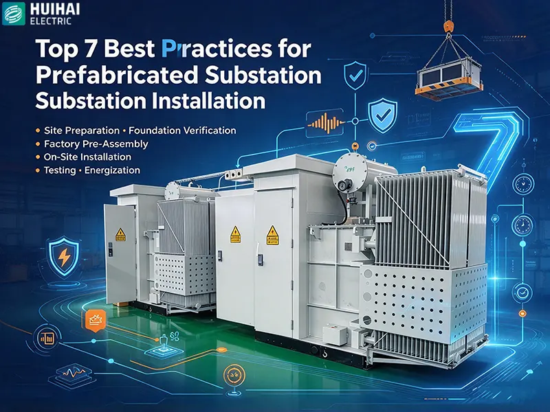
This professional guide presents the top 7 best practices for prefabricated substation installation. Each practice is informed by IEC 62271-202 and industry field experience, and addresses the critical steps from site preparation through final energization.
Best Practice 1: Complete Site Preparation and Foundation Verification Before Delivery
Key principle: The foundation must be level, cured, and verified before the prefabricated substation arrives on site.
Site preparation is the foundation—literally and figuratively—of a successful prefabricated substation installation. Unlike traditional substations where foundation work and equipment installation are sequential phases of a long construction schedule, prefabricated substations compress the on-site timeline dramatically. This compression means that any foundation deficiency discovered after delivery can cause significant delays.
What Site Preparation Involves
- Verifying that the foundation dimensions, elevation, and anchor bolt locations match the approved drawings
- Confirming that the concrete has reached its specified design strength—typically 28-day curing is required before loading
- Checking foundation levelness with a precision level; deviations should not exceed 1 mm per meter
- Verifying that cable trenches, entry points, and earthing connections are in place and correctly positioned
- Ensuring adequate access for delivery vehicles, cranes, and installation equipment
Why This Matters
Prefabricated substations are precision-engineered assemblies. If the foundation is not level, the enclosure may distort, doors may not align, and internal components may experience unintended mechanical stress. Correcting foundation problems after the substation has been delivered requires either lifting the entire unit or performing remedial concrete work on-site—both of which are costly and time-consuming.
The best practice is to conduct a formal foundation inspection with a signed checklist before authorizing delivery. This inspection should be witnessed by the installation supervisor and documented with photographs and level measurements.
Best Practice 2: Verify Factory Acceptance Test Documentation and Component Integrity on Arrival
Key principle: Confirm that the equipment received matches the factory-tested configuration and has not been damaged in transit.
One of the primary advantages of prefabricated substations is that they are factory-assembled and factory-tested before shipment. However, this advantage is only realized if the equipment arrives on-site in the same condition it left the factory—and if the installation team has verified that the delivered configuration matches the approved design.
Arrival Inspection Checklist
- Compare the delivered equipment against the packing list and approved drawings
- Inspect the enclosure for transit damage—dents, scratches, corrosion, or deformation
- Verify that all internal components are secure and have not shifted during transport
- Check that factory acceptance test (FAT) documentation is present and complete
- Confirm that protection relays, meters, and control devices are the specified models
- Verify that all access doors, panels, and covers open and close freely
- Check gas pressure (for GIS-integrated units) and confirm no leaks are evident
Why This Matters
Transit damage is more common than many project teams expect, particularly for large prefabricated substations that travel long distances by road or sea. Internal components may shift, connections may loosen, and enclosure seals may be compromised. Identifying these issues at the arrival inspection stage allows them to be resolved before installation begins—rather than discovering them during commissioning, when remediation is far more disruptive.
Maintain a signed arrival inspection report and photograph any discrepancies. This documentation is essential for warranty claims and for establishing a clear chain of custody.
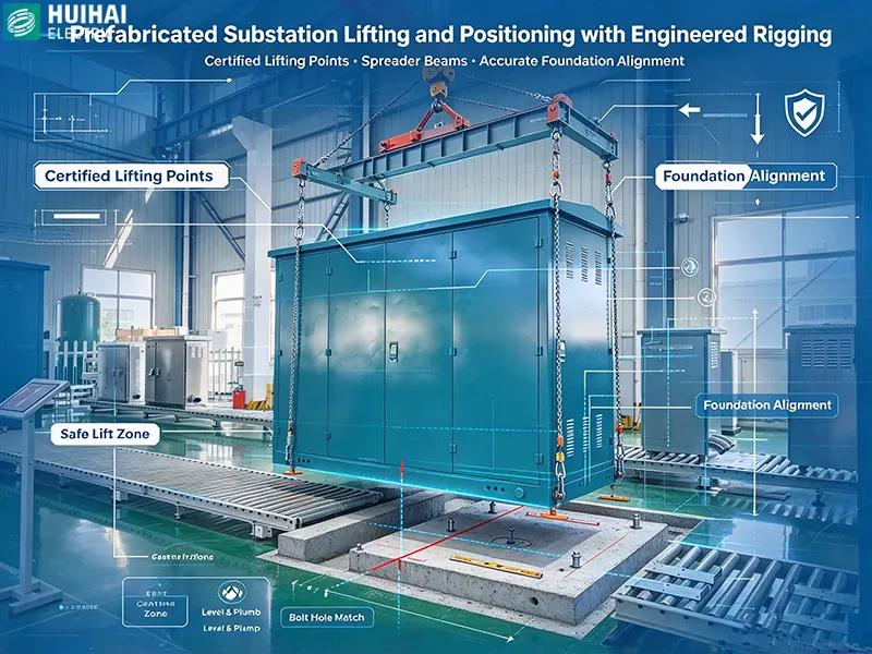
Best Practice 3: Plan Lifting and Positioning with Engineered Rigging
Key principle: Use engineered lifting plans and certified rigging equipment to position the prefabricated substation safely and accurately.
Prefabricated substations are heavy—often weighing several tonnes depending on voltage class, transformer capacity, and enclosure type. Lifting and positioning them requires careful planning and appropriate equipment. Improper lifting can damage the enclosure, distort the frame, or compromise internal components.
Lifting Plan Requirements
- Confirm the unit's weight and center of gravity from the manufacturer's documentation
- Identify designated lifting points—never lift from arbitrary locations on the enclosure
- Select rigging equipment with adequate capacity and certified inspection status
- Use spreader beams where required to prevent lifting slings from contacting the enclosure
- Plan the lifting path to avoid overhead obstacles and ensure adequate crane reach
- Assign a qualified rigger and signal person for the lift
Positioning Accuracy
Once lifted, the prefabricated substation must be positioned accurately on its foundation. Small positioning errors can cause difficulties in cable connection, door alignment, and anchoring. Use guide lines or alignment marks on the foundation to facilitate positioning, and verify alignment before lowering the unit fully onto the foundation.
After positioning, verify that the substation is level in both directions and that all anchor bolt locations align with the foundation provisions. Only then should the unit be secured to the foundation.
Best Practice 4: Execute Primary and Secondary Connections According to Torque Specifications
Key principle: All electrical connections must be made to the manufacturer's specified torque values and verified with calibrated tools.
The electrical connections—both primary power cables and secondary control wiring—are the interface between the prefabricated substation and the wider electrical network. Connection quality directly affects safety, reliability, and long-term performance.
Primary Connections
- Verify cable sizing and termination type against the approved design
- Prepare cable terminations according to the cable manufacturer's instructions
- Clean all contact surfaces and apply conductive paste where specified
- Tighten all bolted connections to the torque values specified by the switchgear or transformer manufacturer
- Mark each tightened connection with a torque seal or paint mark to enable visual verification
Secondary Connections
- Verify control cable schedules against the approved drawings
- Terminate control cables with appropriate ferrules and labels
- Connect protection relay inputs, CT/VT circuits, and communication interfaces according to the manufacturer's wiring diagrams
- Verify polarity and phase relationship for all instrument transformer connections
- Perform insulation resistance tests on secondary circuits before energization
Why Torque Specifications Matter
Under-torqued connections develop high contact resistance, leading to overheating and potential failure. Over-torqued connections can damage threads, strip bolts, or crack insulators. Both conditions are avoidable through the use of calibrated torque wrenches and adherence to the manufacturer's specifications.
Best Practice 5: Verify Earthing and Bonding Integrity Before Energization
Key principle: The earthing system must provide a low-impedance path for fault current and ensure personnel safety under all operating conditions.
Earthing and bonding are critical safety systems in any substation, but they are particularly important for prefabricated substations where the entire electrical installation is contained within a relatively compact enclosure. A deficient earthing system can result in dangerous touch voltages, equipment damage during faults, and protection relay misoperation.
Earthing Verification Steps
- Verify that the main earthing conductor is connected to the station earth electrode system at the designated connection points
- Confirm that all metallic enclosures, frames, and equipment cases are bonded to the main earthing conductor
- Check that cable screens and armouring are earthed at the appropriate points
- Verify that instrument transformer secondary circuits are earthed at one point only, as specified
- Measure earth continuity resistance between all bonded components and the main earthing terminal
- Conduct a fall-of-potential or clamp-on earth resistance test to verify the overall earthing system resistance
Why This Matters
During a fault, the earthing system must carry fault current safely to earth without developing dangerous potential differences across the installation. If earthing is deficient, touch voltages may exceed safe limits, endangering personnel. Protection relays may also fail to operate correctly if the reference earth potential is not stable.
The earthing and bonding verification should be documented with measured values and signed off by the installation supervisor before any energization activity begins.
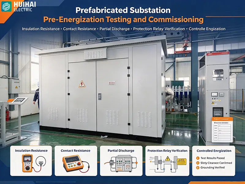
Best Practice 6: Conduct Comprehensive Pre-Energization Testing and Commissioning
Key principle: No prefabricated substation should be energized until all pre-commissioning tests have been completed and documented.
Pre-energization testing is the final verification that the installation has been executed correctly and that the equipment is ready for service. This phase is particularly important for prefabricated substations because the internal wiring and factory-assembled components cannot be fully inspected after the enclosure is sealed.
Pre-Energization Test Sequence
- Visual inspection of the complete installation—check for loose connections, proper earthing, and any signs of damage or improper installation
- Insulation resistance testing of primary and secondary circuits using a megohmmeter
- Contact resistance measurement of primary connections
- Partial discharge measurement—particularly important for cast-resin transformers and GIS components
- Functional testing of protection relays, including trip and alarm verification
- Circuit breaker timing tests and mechanical operation verification
- Verification of interlocking systems and safety features
- Communication system testing—verify SCADA, RTU, and IEC 61850 connectivity
Documentation Requirements
All test results should be recorded on approved test sheets and compared against the manufacturer's acceptance criteria. Any discrepancies must be investigated and resolved before energization proceeds. The completed test documentation becomes part of the project handover package and provides a baseline for future maintenance comparisons.
Best Practice 7: Plan and Execute Energization as a Controlled, Documented Procedure
Key principle: Energization must follow a written procedure with defined hold points, clear communication protocols, and documented verification at each stage.
The final step—energization—is the moment when the prefabricated substation transitions from an installed asset to an operational one. This step should never be rushed or improvised. A controlled, documented energization procedure ensures that all preparatory work has been completed, that personnel are safe, and that any issues are detected and addressed promptly.
Energization Procedure Elements
- Pre-energization briefing with all involved personnel, including the utility representative, installation contractor, and commissioning engineer
- Confirmation that all pre-energization tests have been completed and signed off
- Verification that all personnel are clear of the equipment and that safety barriers are in place
- Application of auxiliary and control power first, with verification of correct operation
- Energization at no load, with verification of voltage and phase sequence
- Progressive loading, with monitoring of temperature, current, and protection system operation
- Final documentation and handover to the operating authority
Post-Energization Monitoring
After energization, monitor the prefabricated substation closely during the first hours and days of operation. Check for abnormal temperature rise, unusual noise, protection relay activity, and communication system performance. Early detection of anomalies allows corrective action before they develop into failures.
Summary: The 7 Best Practices at a Glance
| # | Best Practice | Key Focus | Critical Verification |
|---|---|---|---|
| 1 | Site Preparation and Foundation Verification | Level, cured, and dimensionally accurate foundation | Signed pre-delivery inspection checklist |
| 2 | Arrival Inspection and FAT Documentation | Confirm equipment integrity and match to factory-tested configuration | Signed arrival inspection report with photographs |
| 3 | Engineered Lifting and Positioning | Safe lifting with certified rigging and accurate placement | Level verification and anchor bolt alignment |
| 4 | Primary and Secondary Connections | Torque-controlled connections with calibrated tools | Torque seal marks and contact resistance measurements |
| 5 | Earthing and Bonding Integrity | Low-impedance earth path for fault current and safety | Earth continuity and earth resistance test results |
| 6 | Pre-Energization Testing | Comprehensive verification of electrical and functional performance | Completed and signed test sheets against acceptance criteria |
| 7 | Controlled Energization Procedure | Documented, staged energization with defined hold points | Signed energization checklist and post-energization monitoring report |
Why Installation Quality Determines Prefabricated Substation Performance
The best practices described in this guide are not optional refinements—they are essential steps that determine whether a prefabricated substation delivers the reliability, safety, and longevity that its design intended. The global prefabricated substation market is growing rapidly, with the technology increasingly deployed in urban distribution networks, renewable energy projects, and industrial facilities. As deployment scales, installation quality becomes a critical determinant of overall grid performance.
Prefabricated substations offer significant advantages—faster deployment, factory quality control, compact footprint, and reduced site disruption. But these advantages depend on proper installation. A prefabricated substation that is installed on an inadequate foundation, connected with under-torqued terminals, or energized without comprehensive testing will not deliver the performance that its factory testing promised.
For project owners, EPC contractors, and installation teams, the message is clear: invest in installation planning and execution with the same rigor that is applied to equipment specification. The result will be a prefabricated substation that performs reliably for decades.
How Huihai Electric Supports Professional Installation
Huihai Electric manufactures prefabricated substation equipment designed for straightforward, reliable installation. The company's product portfolio includes intelligent box-type substations, compact-type substations, buried-type substations, and prefabricated substation enclosures in non-metallic landscape, metal, aluminum alloy, and stainless steel configurations.
Installation Support Features
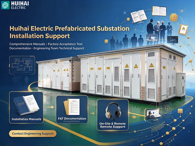
- Comprehensive installation manuals with step-by-step procedures and torque specifications
- Factory acceptance test documentation provided with every unit
- Pre-installed lifting points and clear marking of rigging locations
- Pre-wired and pre-tested internal connections to minimize on-site work
- Standardized connection interfaces for incoming and outgoing cables
- Technical support available from Huihai Electric's engineering team throughout the installation process
Huihai Electric Co., Ltd. was incorporated in 2010 and is located at the foot of Mount Tai in Tai'an City, Shandong Province. The company operates from a modern manufacturing facility covering more than 70 mu with a workshop area of 26,000 square meters. With over 280 staff members, including 57 technical R&D personnel, Huihai Electric has achieved an annual output value exceeding 300 million yuan and serves customers across utility, industrial, and renewable energy sectors.
The company's prefabricated substations are designed and manufactured to comply with IEC 62271-202, IEC 60076, and applicable GB standards, with full type test reports from accredited independent laboratories. Huihai Electric maintains ISO 9001 quality management and ISO 14001 environmental management certifications.
Conclusion
Prefabricated substation installation is a disciplined engineering process that rewards careful planning and thorough execution. The seven best practices presented in this guide—site preparation and foundation verification, arrival inspection, engineered lifting, torque-controlled connections, earthing integrity, pre-energization testing, and controlled energization—provide a framework for installation teams to deliver reliable, safe, and long-lasting prefabricated substation installations.
Whether you are installing a single compact substation for a commercial building or a fleet of intelligent box-type substations for a utility distribution network, these practices apply. They are grounded in IEC standards, validated by field experience, and supported by manufacturers like Huihai Electric who understand that equipment quality and installation quality must work together.
For project teams planning prefabricated substation installations in 2026 and beyond, the investment in professional installation practices pays dividends throughout the equipment's 25-30 year service life—in reliability, safety, and operational efficiency.
Ready to plan your next prefabricated substation installation?
Contact Huihai Electric to discuss your project requirements, request installation documentation, or schedule a technical briefing with our engineering team.
Huihai Electric Co., Ltd.
Editor Xu
www.huihai-electric.com
WhatsApp:+86 139 1136 0187
Email:info@huihai-electric.com
- Avoid Costly Mistakes: 8 Dry-Type Transformer Specs to Verify Before Purchase
- The 9 Key Roles of Dry-Type Transformers in Modern Smart Grid Infrastructure Construction
- The 9 Core Roles of Huihai Electric Prefabricated Substations in Photovoltaic Power Generation Systems
- Best 6 Cost-Effective High Voltage Switchgear for Commercial Power Use
HUIHAIElectric
Huihai Electric is a leading manufacturer of smart grid equipment in China.