Huihai
Electric
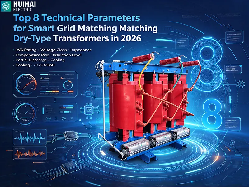
Top 8 Technical Parameters for Smart Grid Matching Dry-Type Transformers
Smart grids are not simply traditional grids with digital meters attached. They are fundamentally different operating environments—characterized by bidirectional power flow, high penetration of distributed energy resources, harmonic-rich loads from inverters and EV chargers, and an expectation of real-time visibility into asset health. In this environment, dry-type transformers that were specified for conventional distribution duties often fall short of what smart grid matching actually requires.
The global dry-type transformer market grew from USD 7.1 billion in 2025 to USD 7.66 billion in 2026 at a CAGR of 7.9%, and is projected to reach USD 10.26 billion by 2030. Another market assessment places the 2026 figure at USD 18.37 billion, rising to USD 24.18 billion by 2031 at 5.65% CAGR. Regardless of the specific data source, the direction is consistent: demand is expanding rapidly, driven by renewable integration, electrification, and smart grid deployment.
But market growth alone does not tell you which parameters determine whether a dry-type transformer is genuinely smart grid matched. This article identifies the top 8 technical parameters that procurement teams, project engineers, and utility asset managers should verify when specifying dry-type transformers for smart grid applications in 2026.
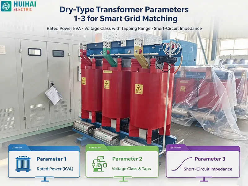
Parameter 1: Rated Power (kVA) and Loading Profile Compatibility
Smart grid indicator: kVA rating selected against measured load profile, with margin for distributed energy resource variability and future expansion.
Rated power in kVA is the most basic parameter of any dry-type transformer, but smart grid matching demands a more sophisticated approach than simply matching nameplate kVA to connected load. Smart grids introduce load variability that traditional design practices did not anticipate: reverse power flow from rooftop solar, pulsed demand from EV fast chargers, and bidirectional energy flows from battery storage systems.
Small ratings up to 10 MVA accounted for 68.8% of the dry-type transformer market share in 2025, and this segment is projected to grow at 8.6% as rooftop solar, EV charging hubs, and battery storage expand. This concentration in smaller ratings reflects the distributed nature of smart grid assets—but it also means that sizing errors have outsized consequences, because these transformers are deployed in large numbers.
What to verify
- Confirm that the kVA rating has been selected against a measured 15-minute or 30-minute load profile, not a simple connected-load calculation
- Verify that the transformer can sustain the expected cyclic loading imposed by renewable generation and EV charging without exceeding temperature limits
- Check whether the manufacturer has sized for harmonic-rich loads using a K-factor rating or equivalent derating methodology
For smart grid applications, a dry-type transformer that is correctly sized for average load but undersized for peak coincident demand will age prematurely. The loading profile, not the nominal kVA figure alone, determines whether the transformer matches the application.
Parameter 2: Voltage Class and Tapping Range
Smart grid indicator: Voltage class matched to system maximum operating voltage, with tapping range sufficient for grid voltage fluctuations caused by distributed generation.
IEC 60076-11 applies to dry-type power transformers with highest voltage for equipment up to and including 72.5 kV and at least one winding operating above 1.1 kV. Within this range, smart grid applications most commonly use medium-voltage dry-type transformers in the 6 kV to 35 kV class, with low-voltage windings at 0.4 kV or similar distribution levels.
Voltage class selection is not simply a matter of matching nominal system voltage. Smart grids with high distributed generation penetration experience wider voltage excursions than conventional radial distribution systems. A dry-type transformer with insufficient tapping range may operate outside its optimal flux density, leading to overheating or premature insulation aging.
What to verify
- Confirm the rated voltage ratio against actual system voltages, including the maximum operating voltage, not just nominal
- Verify that the tapping range—typically ±2×2.5% or wider—can accommodate the expected voltage fluctuations
- Check the insulation level (LI/AC withstand) against the system's overvoltage environment, particularly where capacitor switching or lightning exposure is significant
Smart grid matching requires that the voltage class and tapping arrangement are selected for the grid conditions that will actually exist over the transformer's service life, not for ideal laboratory conditions.
Parameter 3: Short-Circuit Impedance (%Z)
Smart grid indicator: Impedance selected to coordinate with protection settings and limit fault current contribution from distributed generation.
Short-circuit impedance determines both voltage regulation and the magnitude of fault current that the transformer contributes to the grid. In conventional distribution systems, impedance was selected primarily for voltage regulation and protection coordination. In smart grids, impedance takes on additional significance because distributed generation can increase fault current levels beyond what the original network was designed to handle.
Measured values of impedance voltage at the mid-tap position must be in accordance with the standard values set out in IEC 60076-11. Typical impedance values for distribution-class dry-type transformers range from 6% to 8%, with 6% being common for 10 kV/0.4 kV units and higher values for larger or higher-voltage units.
What to verify
- Confirm the guaranteed impedance value and the tolerance band (typically ±10%)
- Verify that the impedance is compatible with the protection settings of the surrounding network, particularly where distributed generation is connected
- Check whether the impedance has been selected to limit fault current contribution to a level that upstream switchgear can safely interrupt
A dry-type transformer with too-low impedance may deliver excellent voltage regulation but contribute excessive fault current in a smart grid with multiple generation sources. A transformer with too-high impedance limits fault current but may cause voltage regulation problems at the end of long feeders. Smart grid matching requires an explicit trade-off analysis, not a default selection.
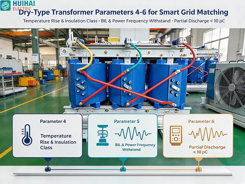
Parameter 4: Temperature Rise Limits and Insulation Class
Smart grid indicator: Temperature rise guaranteed at rated load with margin for cyclic and harmonic loading; insulation class matched to expected hot-spot temperatures.
Temperature rise is the single most important parameter determining dry-type transformer life. Every 10°C increase in operating temperature can halve insulation life. In smart grid applications, temperature rise performance becomes more critical because loading is more variable and harmonic content is higher than in conventional distribution systems.
For cast-resin dry-type transformers, a Class F temperature rise design (100 K) with Class H (180°C) insulation materials provides a significant insulation margin and strong overload capability. This combination—using higher-temperature-capable insulation while limiting temperature rise to a lower value—is a hallmark of dry-type transformers designed for demanding duty cycles. Typical temperature rise limits of 100 K to 125 K are common in smart grid-oriented designs.
What to verify
- Confirm the guaranteed average winding temperature rise and hot-spot temperature rise at rated load and specified ambient temperature
- Verify the insulation class (Class F or Class H) and the corresponding temperature index
- Check whether the manufacturer has evaluated temperature rise under harmonic loading, not just sinusoidal rated current
- Confirm that the temperature rise guarantee is supported by type test reports, not just calculation
A dry-type transformer that meets its temperature rise guarantee at rated sinusoidal load may exceed design temperatures when supplying harmonic-rich loads from PV inverters or EV chargers. Smart grid matching requires temperature rise data that reflects the actual harmonic environment.
Parameter 5: Insulation Level (BIL and Power Frequency Withstand)
Smart grid indicator: Insulation level verified against system overvoltage conditions, including switching surges from capacitor banks and renewable inverters.
Insulation level defines the dry-type transformer's ability to withstand transient overvoltages and power frequency stress. For a 10 kV/0.4 kV unit, a typical insulation level might be LI75AC35—75 kV lightning impulse withstand and 35 kV power frequency withstand. Higher-voltage classes require correspondingly higher insulation levels.
Smart grid applications introduce overvoltage conditions that conventional distribution systems may not experience. Capacitor bank switching for reactive power compensation, inverter-generated switching transients, and the interaction of multiple distributed sources can all produce overvoltage events that stress transformer insulation.
What to verify
- Confirm the basic lightning impulse insulation level (BIL) and power frequency withstand voltage against the system's overvoltage environment
- Verify that the insulation level is adequate for the altitude and pollution conditions at the installation site
- Check that the insulation system has been type-tested, including lightning impulse and power frequency withstand tests
Smart grid matching requires that insulation level is selected for the actual transient environment, not simply the nominal system voltage. A dry-type transformer with marginal insulation level may perform acceptably for years and then fail during an unusual switching event.
Parameter 6: Partial Discharge Level
Smart grid indicator: Partial discharge verified below acceptable limits at 1.3× or higher rated voltage, with test reports from accredited laboratories.
Partial discharge is the most sensitive indicator of insulation quality in dry-type transformers. For cast-resin dry-type transformers rated up to 35 kV, the typical acceptance limit is 10 pC at 1.3× rated voltage. Many high-quality manufacturers achieve significantly lower levels—partial discharge below 5 pC is a common specification for smart grid-oriented products.
Partial discharge matters for smart grid matching because insulation defects that produce elevated PD activity will worsen over time, particularly under the thermal cycling and harmonic stress of smart grid duty. A dry-type transformer that passes routine tests at the factory but has marginal PD performance may develop insulation failure years earlier than expected.
What to verify
- Confirm the guaranteed partial discharge level and the test voltage at which it is guaranteed (typically 1.1×, 1.3×, or 1.5× rated voltage)
- Request partial discharge test reports for the specific unit being purchased, not a generic design report
- Verify that the PD test was performed according to IEC 60076-11 or IEEE C57.12.91 procedures
- Check whether the manufacturer guarantees PD performance after thermal cycling, not just on a new unit
For smart grid applications where dry-type transformers may be installed in unattended or remote locations, low partial discharge is not a premium feature—it is a basic requirement for reliable long-term operation.
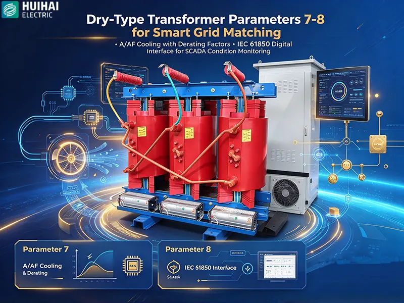
Parameter 7: Cooling Method and Thermal Management
Smart grid indicator: Cooling method (AN, AF, or AN/AF) matched to load profile and installation environment, with derating factors specified for restricted airflow.
Cooling method determines the dry-type transformer's continuous rating and overload capability. Air Natural (AN) cooling relies on natural convection and is suitable for steady loads in well-ventilated locations. Air Forced (AF) cooling uses fans to increase heat dissipation, enabling a higher rating from the same physical core and coil. Dual-rated AN/AF transformers provide both a base rating (AN) and an increased rating with fans operating (AF).
Smart grid applications often benefit from AN/AF dual-rated dry-type transformers because the AF rating provides headroom for peak loads without the losses associated with operating fans continuously. In a smart grid with EV charging or renewable peaks, the AF rating can be used during high-demand periods while the AN rating serves normal loads.
What to verify
- Confirm the cooling class (AN, AF, or AN/AF) and the corresponding kVA ratings for each mode
- Verify the derating factors for restricted airflow, high ambient temperature, and altitude
- Check the fan control strategy—manual, temperature-controlled, or remote—and its compatibility with smart grid control systems
- Confirm that the temperature rise guarantees apply under both AN and AF operating modes
A dry-type transformer with AF cooling may be rated at 125% of its AN capacity, but this increased rating is only valid when fans are operating and airflow is unobstructed. Smart grid matching requires that the cooling method and derating factors are specified for the actual installation conditions, not idealized laboratory conditions.
Parameter 8: Digital Interface and Monitoring Readiness (IEC 61850)
Smart grid indicator: Native support for IEC 61850, with sensor interfaces for temperature and partial discharge and data models compatible with SCADA and distribution management systems.
The digital interface is what separates a smart grid-matched dry-type transformer from a conventional unit. IEC 61850 is the international standard for communication networks and systems in substations, and it has become the baseline requirement for smart grid interoperability. Transformers equipped with IEC 61850 interfaces can communicate directly with substation automation systems, enabling remote monitoring, condition-based maintenance, and participation in grid automation schemes.
Modern intelligent dry-type transformers integrate sensing and monitoring technology to collect transformer characteristic data, store and analyse it, and support fault self-diagnosis—improving the predictability and reliability of the grid. The digital interface is the mechanism through which this data reaches the systems that need it.
What to verify
- Confirm that the transformer provides an IEC 61850 interface, preferably supporting both MMS and GOOSE services
- Verify the sensor package—at minimum, winding temperature and partial discharge monitoring, with options for vibration and gas density where applicable
- Check that the data model is documented and compatible with the utility's SCADA or distribution management system
- Confirm whether condition monitoring data is available locally at the transformer and remotely through the communication interface
A dry-type transformer without a digital interface can still perform its basic voltage transformation function, but it cannot participate in smart grid operations. For projects where condition-based maintenance, remote diagnostics, or automated grid management are requirements, the digital interface is as important as any electrical parameter.
Summary: The 8 Parameters at a Glance
| # | Parameter | Smart Grid Matching Focus | Typical Values / Requirements |
|---|---|---|---|
| 1 | Rated Power (kVA) | Loading profile, DER variability, harmonic duty | Selected against measured load profile; K-factor where needed |
| 2 | Voltage Class and Tapping | Grid voltage fluctuations from distributed generation | Up to 72.5 kV per IEC 60076-11; ±2×2.5% or wider tapping |
| 3 | Short-Circuit Impedance (%Z) | Protection coordination and fault current limitation | Typically 6–8%; verified per IEC 60076-11 standard values |
| 4 | Temperature Rise / Insulation Class | Cyclic and harmonic loading tolerance | Class F rise (100 K) with Class H insulation; verified by type test |
| 5 | Insulation Level (BIL / AC) | Switching and inverter-generated overvoltages | Matched to system overvoltage environment, altitude and pollution |
| 6 | Partial Discharge | Long-term insulation reliability under thermal cycling | ≤10 pC at 1.3× rated voltage; high-quality units <5 pC |
| 7 | Cooling Method | Peak load headroom without continuous fan losses | AN/AF dual-rated; derating specified for actual site conditions |
| 8 | Digital Interface (IEC 61850) | SCADA integration, condition monitoring, grid automation | Native IEC 61850; temperature and PD sensor data available |
Why These 8 Parameters Matter Together
Smart grid matching is not achieved by optimizing any single parameter in isolation. A dry-type transformer with excellent partial discharge performance but inadequate impedance coordination will still fail to match the grid's protection scheme. A transformer with a full IEC 61850 interface but marginal temperature rise performance will deliver data on its own premature aging rather than useful condition intelligence.
The eight parameters interact. Impedance affects temperature rise through fault current contribution. Temperature rise affects insulation life and therefore partial discharge performance over time. Cooling method determines the kVA rating available under different load conditions. The digital interface determines whether any of these performance characteristics can be monitored and managed over the transformer's service life.
Smart grid matching therefore requires a specification process that evaluates all eight parameters against the actual grid conditions, load profile, and automation architecture—not a procurement checklist that treats each parameter independently.
How Huihai Electric Supports Smart Grid Matching
Huihai Electric manufactures dry-type transformers designed for the technical requirements of smart grid applications. The company's product portfolio addresses the eight parameters described in this article:
- Rated power and voltage class configurations covering typical medium-voltage smart grid applications, with tapping arrangements selected for grid voltage conditions
- Short-circuit impedance verified in accordance with IEC 60076-11 requirements, with values coordinated to the project's protection scheme
- Temperature rise and insulation class designs that provide margin for cyclic loading, supported by type test documentation
- Partial discharge performance controlled to low pC levels, with test reports available for the specific unit
- Cooling method options including AN/AF configurations, with derating factors specified for actual installation conditions
- Digital monitoring readiness for integration with smart grid communication architectures, supporting condition data availability for SCADA and asset management systems
Huihai Electric's dry-type transformers are manufactured under ISO 9001 quality management and ISO 14001 environmental management systems, with full type test reports from accredited laboratories. For smart grid projects where dry-type transformers must match both electrical performance requirements and digital communication expectations, Huihai Electric provides a compliant, documented, and application-focused solution.
Need to specify dry-type transformers for a smart grid project?
Contact Huihai Electric to discuss your kVA, voltage class, impedance, temperature rise, partial discharge, cooling, and IEC 61850 requirements.
Huihai Electric Co., Ltd.
Editor Xu
www.huihai-electric.com
WhatsApp:+86 139 1136 0187
Email:info@huihai-electric.com
HUIHAIElectric
Huihai Electric is a leading manufacturer of smart grid equipment in China.