Huihai
Electric
The 7 Major Causes of Excessive No-Load Current in Dry-Type Transformers
When a dry-type transformer operates under no-load conditions at its rated voltage, the current flowing through the primary side is called the no-load current. Normal no-load current is typically only 2% to 5% of the rated current. It is mainly used to establish the main magnetic flux in the core. Although the value is small, it directly reflects the overall quality of the transformer core material, magnetic circuit structure, and assembly process. When the no-load current exceeds 8% of the rated current or even reaches 10% or more, it means that the internal losses of the core have increased significantly. This not only causes abnormal heating and excessive temperature rise in the transformer body but also reduces the system power factor. In severe cases, it can even accelerate insulation aging or cause malfunctions of protection devices. Therefore, accurately identifying the root causes of excessive no-load current is crucial for the safe operation and fault prediction of dry-type transformers. Based on field operation and maintenance experience and theoretical analysis, the following seven major causes can be summarized:
1. What is a Dry-Type Transformer?
1.1. Basic Definition
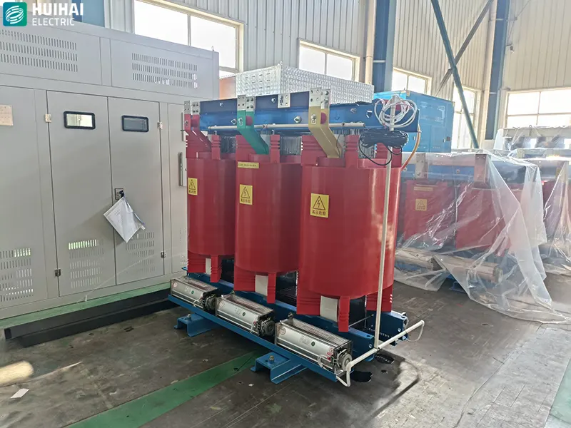
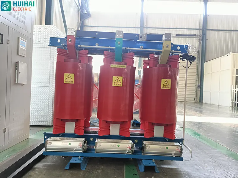
A dry-type transformer is a transformer whose core and windings are not immersed in any insulating liquid (such as transformer oil). Its core and coils are either directly exposed to the air or encapsulated with solid insulating materials such as epoxy resin, relying on air convection or forced cooling for heat dissipation.
1.2. Main Structure
- Core: Typically made of stacked high-permeability cold-rolled silicon steel sheets to reduce hysteresis and eddy current losses.
- Windings: Generally divided into high-voltage and low-voltage windings, mostly made of copper conductors, and vacuum-cast or encapsulated with insulating materials such as epoxy resin to form a robust solid insulation layer.
- Outer Shell: Usually equipped with a protective outer shell (IP20, IP23, etc.) for safety and dust protection.
1.3. Key Differences Between Dry-Type and Oil-Immersed Transformers
| Characteristics | Dry-Type Transformer | Oil-Immersed Transformer |
| Insulation Medium | Air, epoxy resin, or other solid insulation | Transformer oil (mineral oil or vegetable oil) |
| Heat Dissipation Method | Natural air cooling (AN) or forced air cooling (AF) | Natural oil circulation, forced oil circulation, air cooling, etc. |
| Installation Location | Indoor (for locations requiring fire and explosion protection, such as high-rise buildings, subways, data centers, hospitals) | Outdoor or independent oil pit/substation |
| Safety | No risk of oil leakage, not easily combustible or explosive | Oil is flammable, posing a risk of leakage and fire |
| Maintenance | Simple maintenance, no need for oil filtration or oil chromatography analysis | Requires periodic oil sampling and testing, and replacement of aged oil |
| Noise | Relatively slightly higher (due to the lack of oil damping) | Relatively lower |
| Overload Capacity | 1. Weak short-term overload capacity, high ventilation requirements | Oil has high heat capacity, strong short-term overload capacity |
| Cost | Generally more expensive than oil-fired transformers for the same capacity | Relatively economical |
2. Advantages and disadvantages of dry-type transformers
2.1. Advantages:
- No risk of oil leakage, environmentally friendly
- Flame retardant, self-extinguishing, high safety
- Low maintenance workload
- Can be directly installed at the load center, reducing cable length
2.2. Disadvantages:
- Slightly larger in size and weight compared to oil-fired transformers of the same capacity
- Higher noise
- Certain requirements for operating environment humidity and dust (unless enclosed or with special protection level)
- Higher price
3. Reasons for excessive no-load current
3.1. Excessive power supply voltage
- Mechanism: Voltage increase → Core magnetic flux density (B) exceeds design limit → Enters saturation → Excitation current rises sharply.
- Data Reflection:
- Voltage exceeding rated value by 5%: I0 increases by 30%–50%.
- Voltage exceeding rated value by 10%: I0 increases by 80%–150%, even exceeding 20% of IN.
- Three-phase voltage imbalance >2%: No-load current three-phase imbalance >10%.
3.2. Insulation damage between silicon steel sheets in the core
- Mechanism: Aging, damage, and overheating of the inter-sheet insulation varnish → Inter-sheet short circuit → Significant increase in eddy currents.
- Data Reflection:
- Local insulation damage: I0 increases by 50%–100%, no-load loss P0 increases by 40%–80%.
- Multiple short circuits/burning: I0 can reach 2–5 times the normal value, core temperature rise exceeds 80K.
- Core grounding current >100mA (normal < 10mA).
3.3. Loose core laminations, excessive air gap
- Mechanism: Insufficient clamping force, large joints, uneven laminations → increased air gap in the magnetic circuit → increased magnetic reluctance → increased excitation current.
- Data manifestation:
- Loose laminations, joints exceeding 0.5mm: I0 increases by 40%~80%.
- Overall air gap increases by 0.1mm: I0 increases by approximately 20%.
- Significantly increased noise (humming sound), vibration velocity >2.5mm/s.
3.4. Inter-turn/inter-layer short circuit in windings
- Mechanism: Insulation aging, moisture, partial discharge → inter-turn short circuit → reduced effective turns → increased magnetic flux density → increased excitation current.
- Data Reflection:
- Minor inter-turn short circuit (1-2 turns): I0 increases by 30%-60%, three-phase imbalance >15%.
- Severe short circuit: I0 reaches 2-4 times the normal value, no-load loss P0 increases by 100%-300%.
- Partial discharge >500pC (normal < 100pC).
3.5. Multiple-point grounding of the core or damage to the insulation of clamps
- Mechanism: Damage to the insulation of the through bolts, clamps, and pressure plates → multiple-point grounding of the core → closed circulating current → increased loss and current.
- Data Reflection:
- Two-point grounding: I0 increases by 50%-120%, grounding current 50-200mA.
- Clamping short circuit: I0 increases by 80%–200%, clamping temperature rise exceeds 60K.
- Insulation resistance (core to ground) < 1MΩ (normal > 100MΩ).
3.6. Design/Manufacturing Defects
- Mechanism: Overly high B value in design (>1.7T), insufficient core cross-section, and low-grade silicon steel sheet → approaching saturation under normal voltage.
- Data Reflection:
- Design magnetic flux density 1.7–1.8T (standard 1.5–1.6T): I0 reaches 12%–20% IN.
- Core cross-section 10% smaller: I0 increases by 40%–70%.
- Using inferior silicon steel sheets (loss > 1.5W/kg): I0 is 30%–80% higher than genuine products.
3.7. Harsh Environment and Long-Term Aging
- Mechanism: High temperature, humidity, dust, corrosion → Aging and moisture absorption of winding and core insulation → Increased dielectric loss and leakage conduction → Increased no-load current.
- Data Reflection:
- Long-term ambient temperature > 40℃: I0 increases by 5%–10% annually.
- Moisture absorption (insulation resistance decreases by 50%): I0 increases by 20%–50%, dielectric loss (tanδ > 5%).
- Operation exceeding 15 years: I0 is 30%–100% higher than newer units.
4. Quick Judgment Reference Table
| No-load Current I0 | Common Causes |
| < 8% IN | Normal Range |
| 8%~15% IN | High Voltage, Slight Loosening, Aging |
| 15%~30% IN | Inter-laminar Insulation Damage, Inter-turn Micro-short Circuit, Multiple Grounding Points |
| >30% IN | Severe Inter-turn Short Circuit, Core Erosion, Design Defects |
5. How to Reduce the No-load Current of Dry-type Transformers
5.1. Real-time Adjustment on the Operating Side
5.1.1. Control Input Voltage to Avoid Core Saturation
- Standard Requirements: Operating voltage controlled within ±5% of rated voltage, three-phase voltage imbalance ≤2%.
- Remedial Measures:
- Adjust the distribution busbars and tap changers; long-term overvoltage operation is strictly prohibited; immediately reduce the load when the voltage exceeds the rated value by 10%.
- If the three-phase voltage difference exceeds the standard, check the lines and compensation devices, and balance the three-phase load.
- Result: After the voltage returns to the rated value, the no-load current can drop by 30%~80%.
5.1.2. Improve the operating environment, prevent moisture, control temperature, and reduce aging.
- Standard thresholds: Ambient temperature ≤40℃, relative humidity ≤85%, no condensation, dust, or corrosive gases.
- Remedial Measures:
- Install ventilation fans and exhaust systems; force ventilation in high-temperature environments;
- Install dehumidification equipment indoors; ensure proper sealing and moisture prevention during shutdowns;
- Regularly clean dust accumulation on the iron core and winding surfaces.
- Result: After the damp equipment dries, the no-load current decreases by 20%~50%.
5.2. Disassembly, Inspection, and Repair
5.2.1. Handling Multiple Grounding Points in the Iron Core and Insulation Faults in Clamping Components
- Acceptance Criteria: Iron core insulation resistance to ground > 100MΩ, iron core grounding current < 10mA.
- Remedial Measures:
- Locate and remove redundant grounding points, leaving only one reliable grounding point;
- Repair damaged insulation in clamping components, through bolts, and pressure plates, and reapply insulating varnish;
- When the grounding current is 50~200mA, systematically check for and isolate short-circuit points.
- Result: After fault elimination, the no-load current drops by 50%~200%.
5.2.2. Tightening the Iron Core Laminations and Eliminating Excessive Air Gap
- Acceptance Criteria: Lamination joint gap ≤ 0.5mm, no overall looseness, vibration velocity ≤ 2.5mm/s.
- Remedial Measures:
- Evenly tighten the core clamping bolts to ensure consistent overall clamping force;
- Realign misaligned laminations, fill excessively large joints, and reduce the air gap in the magnetic circuit;
- If the loosening is severe, reassemble the silicon steel sheets.
- Results: After air gap rectification, the no-load current decreased by 40%~80%.
5.2.3. Repairing Inter-Layer Insulation of Silicon Steel Sheets
- Acceptance Criteria: No significant surge in core no-load loss, no localized overheating or blackening.
- Remedial Measures:
- Localized insulation damage: Disassemble the damaged area and apply high-temperature resistant insulating varnish;
- Large-area inter-laminar short circuits and ablation: Replace the damaged silicon steel sheets and reassemble;
- Results: After insulation repair, eddy current losses decreased, and the no-load current decreased by 50%~100%.
5.2.4. Handling Inter-turn/Inter-layer Short Circuits in Windings
- Acceptance Criteria: Partial discharge < 100pC, three-phase no-load current imbalance ≤ 10%.
- Remedial Measures:
- Minor inter-turn insulation degradation: Drying and vacuum impregnation to strengthen insulation;
- Identifying inter-turn short circuits: Disassemble the winding, replace the damaged coil, and rewind;
- Result: After the short circuit fault is eliminated, the no-load current can return to the normal range.
5.3. Equipment Upgrades and Technical Modifications
5.3.1. Replacing with High-Grade, Low-Loss Silicon Steel Sheets
- Applicable Scenarios: Original core magnetic flux density is too high (> 1.6T), and silicon steel sheet losses are high.
- Selection Criteria: Select oriented high-permeability silicon steel sheets, with unit loss ≤ 1.2W/kg, and design magnetic flux density controlled between 1.5 and 1.6T.
- Result: Compared to inferior silicon steel sheets, the no-load current is reduced by 30% to 80%.
5.3.2. Optimize Core Structure and Increase Effective Cross-Section
- Applicable Scenarios: Equipment with a small core cross-section and inherently high magnetic reluctance.
- Solution: Within the structural limits, appropriately increase the core cross-sectional area to reduce magnetic flux density and avoid magnetic circuit saturation.
- Effect: A 10% increase in cross-section can reduce no-load current by 40%~70%.
6. Daily Operation and Maintenance Management of Dry-Type Transformers
- Regular Inspection: Measure no-load current, core grounding current, and insulation resistance quarterly, establish a data ledger, and immediately investigate any current increase exceeding 15% for a single unit.
- Periodic Maintenance: Conduct a comprehensive dust removal and tighten connections annually; perform a special insulation aging test after 10 years of operation.
- Load Management: Avoid long-term overvoltage and overload operation of transformers, and prevent frequent impact loads.
- Warehouse/Shutdown Protection: Ensure long-term shutdown equipment is properly sealed and moisture-proofed, and briefly energize monthly to remove moisture.
7. Simplified Quick Reference Table
| Main Problems | Core Handling Methods | No-Load Current Reduction |
| Overvoltage/Three-phase imbalance | Adjust tap changer, balance three-phase voltage | 30%~80% |
| Multiple grounding points in the core | Rectify grounding points, repair clamp insulation | 50%~200% |
| Loose core laminations, large air gap | Tighten bolts, straighten laminations | 40%~80% |
| Damaged silicon steel sheet insulation | Touch-up painting/replace silicon steel sheets | 50%~100% |
| Short circuit between winding turns | Impregnation repair/rewinding coil | Restore to normal value |
| Moisture, dust accumulation | Ventilation and dehumidification, thorough dust removal | 20%~50% |
| Design defects (high magnetic flux density/inferior core) | Replace with low-loss silicon steel sheets, increase core cross-section | 30%~80% |
8. Conclusion
Based on operational, structural, insulation, and environmental dimensions, seven core causes and key characteristics are summarized:
- Excessive Operating Voltage: Voltage exceeding rated values or three-phase imbalance leads to core magnetic flux saturation and a significant increase in no-load current, the most common cause.
- Damaged Insulation Between Silicon Steel Sheets: Inter-sheet short circuits cause a surge in eddy currents, resulting in a simultaneous increase in no-load losses and current, accompanied by localized core heating.
- Loose Core Laminations and Excessive Air Gap: Increased magnetic reluctance leads to higher excitation current, significantly increasing equipment vibration and noise.
- Inter-turn/Inter-layer Short Circuits in Windings: Reduced effective turns result in abnormally high magnetic flux density and increased deviation in three-phase no-load current.
- Multiple Core Grounding Points and Damaged Clamp Insulation: Formation of closed-loop currents generates additional losses, with grounding currents far exceeding standard values.
- Design and manufacturing defects: Excessively high core flux density, insufficient cross-section, or use of inferior silicon steel sheets can lead to inherent saturation issues in the equipment.
- Harsh environment and equipment aging: Moisture, high temperature, and dust accumulation accelerate insulation deterioration, causing the no-load current to increase year by year during long-term operation.
In summary, excessive no-load current in dry-type transformers is not caused by a single factor, but rather by a combination of factors including silicon steel sheet material, core manufacturing process, winding design, insulation condition, power supply conditions, and the external environment. For every percentage point increase in no-load current, iron losses multiply. Long-term operation will not only shorten the transformer's lifespan but may also induce localized overheating, inter-turn short circuits, and even burnout. Therefore, in daily operation and maintenance, the no-load current and its harmonic components should be measured regularly, and cross-checked with parameters such as no-load loss, noise, temperature rise, and core grounding current. If an excessive no-load current is detected, check the following seven possible causes one by one: First, check if the power supply voltage is too high; then test the core insulation and grounding system; if necessary, lift the core to check the inter-core condition and the number of winding turns. Timely location and elimination of potential faults are crucial to ensuring that the dry-type transformer always operates in a low-loss, high-reliability state.
Written by
Huihai Electric Co., Ltd.
Editor Xu
www.huihai-electric.com
WhatsApp:+86 139 1136 0187
Email:info@huihai-electric.com
HUIHAIElectric
Huihai Electric is a leading manufacturer of smart grid equipment in China.