Huihai
Electric
9 Important Considerations for Outdoor Installation of Power Transformers
As a high-tech enterprise and a specialized and innovative medium-sized enterprise, Huihai Electric has been deeply involved in the R&D, production, and sales of power equipment for many years. Always adhering to the core principle of "zero-defect quality," and upholding the concepts of green manufacturing and safe operation and maintenance, Huihai Electric relies on a comprehensive quality management system and profound technical accumulation to provide reliable transformer products and professional installation guidance for various power scenarios. As a core hub of the power system, the outdoor installation environment of power transformers is complex and variable, affected by multiple factors such as terrain, climate, and electrical environment. The installation quality directly determines the stability, safety, and service life of the equipment. To standardize the outdoor installation process of Huihai Electric power transformers, prevent installation hazards, and ensure the long-term safe and efficient operation of the equipment, this document outlines nine important considerations based on relevant international standards and the company's many years of experience in installing new energy power facilities. These considerations are for installation personnel to strictly follow.
1. Foundation and Ground Site Selection
1.1. Site Selection Environment and Details
- Topography: Prioritize high-lying, dry, and flat areas. Avoid low-lying, pitted areas, areas prone to water accumulation during the rainy season, areas susceptible to flash floods, landslides, and subsidence. The ground should have a natural drainage slope to prevent water accumulation and soaking of the base.
- Avoid Dangerous Areas: Keep away from flammable and explosive warehouses, gas stations, chemical plants, areas with corrosive gases, and areas with dust pollution. Avoid areas with strong vibrations and frequent heavy machinery operations to prevent vibration damage to the transformer core and insulation.
- Surrounding Safety Distances: Maintain a standard safe distance from buildings, walls, trees, roads, and overhead power lines. Avoid locations with high pedestrian traffic or where children can easily climb and approach, facilitating future operation and maintenance.
1.2. Foundation Construction Details
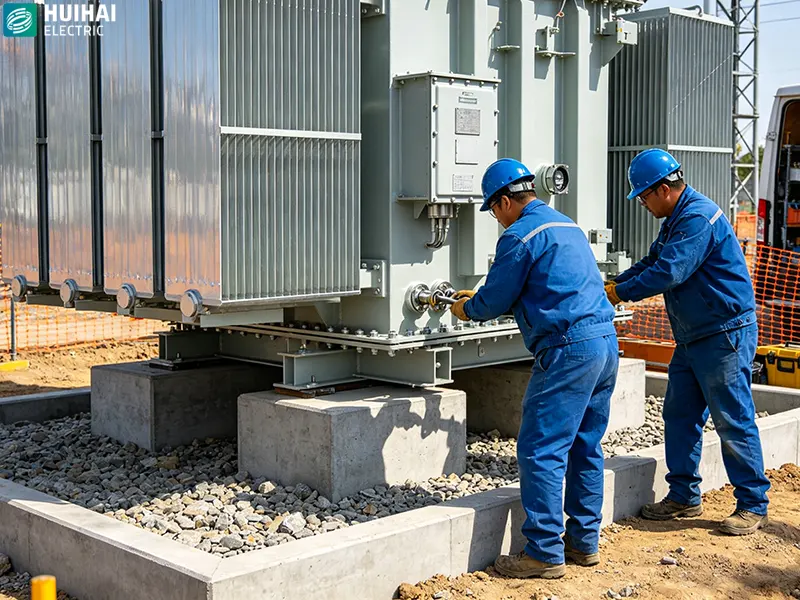
- Foundation Types: Commonly used outdoor foundations include independent concrete foundations, strip foundations, and platform foundations. The foundation should be designed to bear the load according to the transformer's capacity and weight, and the ground should be compacted to prevent future settlement and tilting.
- Elevation and Slope: The top surface of the foundation should be at least 300mm higher than the natural ground level, with a 2%–3% outward slope for drainage to ensure rapid rainwater drainage and prevent accumulation around the transformer base.
- Dimensional Provisions: The foundation's length and width should exceed the transformer base on each side by 200–300mm. Anchor bolts must be precisely embedded and aligned, ensuring uniform elevation and overall levelness.
- Smoothness and Strength: Concrete grade must meet standards, and curing must be adequate. The levelness error of the foundation's top surface should be controlled within 5mm to prevent misalignment or tilting that could cause equipment deformation or oil leaks.
1.3. Ground and Drainage Details
- Surrounding Ground Treatment: A hardened concrete ground or gravel slope should be constructed around the transformer to prevent weed growth and rainwater erosion that could hollow out the foundation.
- Drainage Facilities: Drainage ditches and slopes should be installed around the perimeter to direct rainwater to municipal sewer systems or low-lying ditches, strictly prohibiting prolonged soaking of the foundation base by rainwater.
- Corrosion Prevention and Protection: Exposed parts of the foundation should be plastered with cement mortar and treated with anti-corrosion measures; in saline-alkali areas, salt-isolation and anti-corrosion measures should be implemented to prevent corrosion of the foundation reinforcement and grounding electrode.
1.4. Post-Construction Details
- Sufficient maintenance and operation space should be reserved around the foundation to ensure unimpeded hoisting, testing, and emergency repairs.
- Pre-planned locations for grounding flat steel embedding and cable trench entry/exit holes should be provided, ensuring proper planning from the outset and avoiding future foundation demolition.
2. Safety Distance Compliance
Basic requirements and authoritative data on safety distances for outdoor power transformers are provided, all of which are practical and usable on-site indicators.
2.1. Basic Requirements
- Electrical Safety Clearance: Prevents electric shock and air breakdown discharge during normal/fault conditions.
- Fire Protection Distance: Oil-immersed transformers should be fireproof and explosion-proof to prevent the spread of fire.
- Maintenance and Protection Distance: Meets requirements for fencing, access, heat dissipation, and maintenance space.
2.2. Core Safety Distance Data (Net Distance, Unit: m)
2.2.1. Transformer Outline to Building
- 10kV Oil-Immersed (Outdoor Ground-Mounted): ≥3.0m from fire-resistant building exterior walls, ≥5.0m from combustible/civilian building exterior walls.
- 35kV oil-immersed transformer: ≥8.0.
- Dry-type/box-mounted transformer (10kV): ≥3.0.
2.2.2. Transformer to fence/wall
- Fence height: ≥1.8 (fixed fence/wall).
- Transformer outer perimeter to fence inner side: ≥0.8.
- Transformer bottom to ground: ≥0.3.
2.2.3. Between adjacent transformers
- Oil weight < 1000kg: Clearance ≥1.5.
- 1000kg ≤ Oil weight ≤2500kg: Clearance ≥3.0.
- Oil weight >2500kg: Clearance ≥5.0.
- Primary load power supply: Regardless of oil weight, clearance ≥5.0; if insufficient, install a firewall.
2.2.4. Transformer to road/access route
- To the edge of the factory road: ≥1.5.
- To the edge of the city road: ≥2.0.
- Main access width: ≥1.5 (handling + maintenance).
2.2.5. Transformer to Trees/Live Conductors
- To Trees (after pruning): ≥1.5 (to prevent contact and falling).
- Safe distance from 10kV bare live conductors to ground: ≥0.7 (personal activity range).
- Safe distance from 35kV bare live conductors to ground: ≥1.0.
2.2.6. Fire Separation Distance (with Flammable Materials/Storage Areas)
- To Combustible Material Storage Areas/Warehouses: ≥10.0.
- To Gas Stations/Chemical Zones: ≥15.0 with isolation facilities.
3. Grounding System Specifications
3.1. Basic Requirements for Grounding Components
- The metal casing of the transformer must be reliably grounded.
- The neutral point on the low-voltage side must be reliably grounded.
- The grounding terminals of high- and low-voltage surge arresters must be reliably grounded.
3.2. Standard Data for Grounding Resistance
- 10kV Distribution Transformer: Grounding Resistance ≤4Ω.
- 35kV Transformer: Grounding Resistance ≤10Ω.
- Multiple Transformers Sharing a Grounding Grid: Controlled according to the minimum standard, still ≤4Ω.
- High Soil Resistivity, Sandy and Gravelly Mountainous Areas: Allowed relaxation, but the maximum should not exceed 10Ω, resistance reduction treatment is mandatory (resistance reducing agent, extended grounding, deep well grounding).
3.3. Grounding Material and Specifications
- Grounding Flat Steel: Hot-dip galvanized flat steel ≥-50×5mm.
- Grounding Electrode: Galvanized angle steel ∠50×50×5mm, length 2.5m/piece.
- Grounding Down Conductor: Flat steel of the same specification or ≥25mm² multi-strand copper core insulated wire.
- Welding Requirements: Lap length ≥ twice the width of the flat steel, full welding on three sides, anti-corrosion and anti-rust treatment after welding.
3.4. Construction Specification Details
- Grounding Electrode Burial Depth: Not less than 0.8m underground, in frost-free soil layers, it must be buried below the frost line.
- The grounding main line is arranged in a ring around the transformer foundation to form a closed grounding network.
- All grounding connections must be individually connected to the grounding network, avoiding loose bolt connections and series connections.
- In saline-alkali or corrosive areas: increase the cross-section of the grounding electrode, add an anti-corrosion coating, and regularly test the grounding resistance.
4. High and Low Voltage Wiring Process
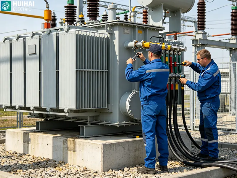
Use qualified insulated wires/copper busbars for the leads; crimp the terminals securely and add spring washers; ensure phase wires are neatly arranged with uniform curvature, avoid forced tension, and maintain intact insulation sheaths to prevent phase-to-phase short circuits and discharge to ground.
5. Surge Arresters and Lightning Protection
High and low voltage surge arresters must be installed outdoors, close to the transformer, with short, straight leads and minimal bends; in areas prone to thunderstorms, additional grounding reinforcement measures can be added to prevent lightning overvoltage breakdown of equipment.
6. Moisture, Dust, and Sun Protection
Use fully sealed outdoor transformers whenever possible; for outdoor installations, provide shade and rain protection to prevent prolonged exposure to direct sunlight, which can accelerate insulation aging; ensure terminal boxes and junction boxes are tightly sealed to prevent rainwater, dust, and small animals from entering.
7. Temperature Control and Ventilation
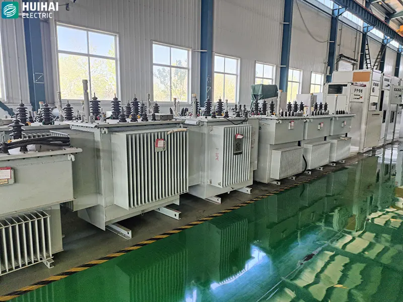
Allow sufficient ventilation space around the transformer; do not pile up debris, straw, or building materials that may obstruct the heat sink; in high-temperature summer environments, install auxiliary ventilation and heat dissipation facilities as needed to prevent overload, overheating, and tripping.
8. Protection and Prevention of Small Animals
Seal the base and openings to prevent snakes, rats, and birds from entering and causing short circuits; do not plant tall trees nearby to prevent branches from touching live parts and causing accidents.
9. Pre-Commissioning Inspection and Testing
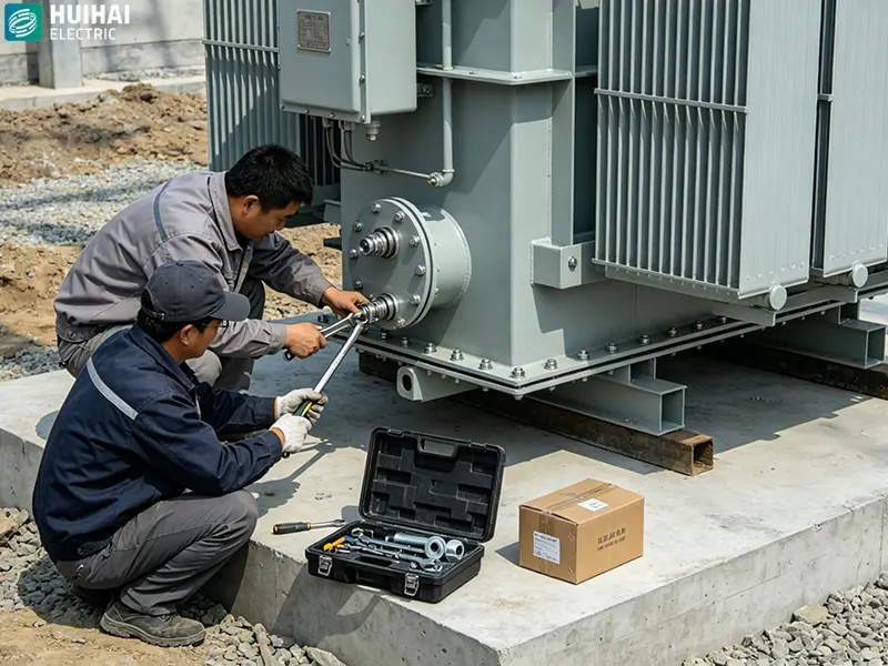
After installation, check the wiring, grounding, insulation, oil level (for oil-immersed transformers), and sealing condition item by item; only after passing insulation resistance, DC resistance, and withstand voltage tests can the transformer be switched on and energized; blind commissioning without acceptance testing is strictly prohibited.
The above nine points of attention are core operating guidelines formulated by Huihai Electric based on years of experience in smart grid equipment R&D and installation, combined with relevant national standards and specifications. They cover key nodes and safety points throughout the entire outdoor installation process. During installation, it is essential to adhere to Huihai Electric's philosophy of "lean management and safety first," strictly implement every operational requirement, and meticulously control every detail to ensure that the installation quality meets the company's 99.97% or higher pass rate for finished products, while also satisfying the core needs of on-site safety, compliance, and convenient operation and maintenance. Huihai Electric will continue to leverage technological innovation to provide professional technical support for installation, working hand-in-hand with construction teams to strengthen power safety defenses, contribute to the stable operation of new energy power systems, and provide customers with more reliable and efficient power equipment and services, fulfilling its corporate mission of "providing customers with exceptional service."
Written by
Huihai Electric Co., Ltd.
Editor Xu
www.huihai-electric.com
WhatsApp:+86 139 1136 0187
Email:13705388456@163.com
HUIHAIElectric
Huihai Electric is a leading manufacturer of smart grid equipment in China.