Huihai
Electric
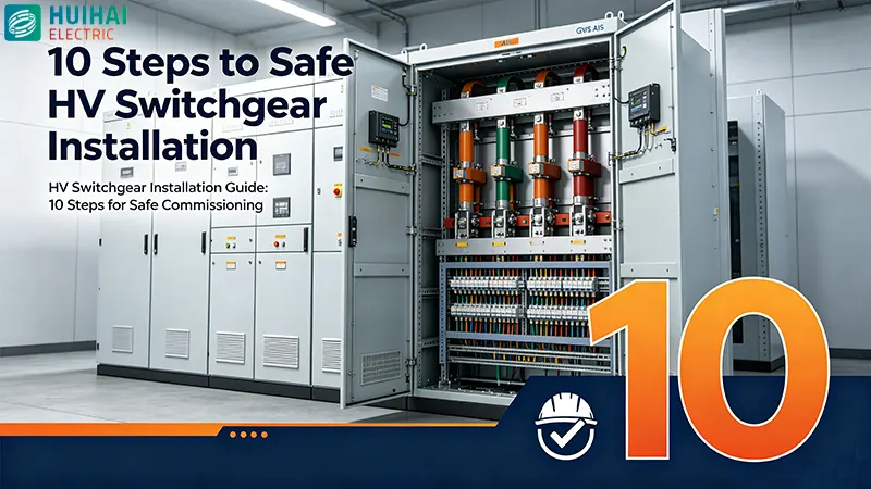
High Voltage Switchgear Installation Guide: 10 Steps for Safe and Reliable Commissioning
Follow this 10-step high voltage switchgear installation and commissioning guide—from site preparation and mechanical alignment to electrical testing and safe energization—for reliable, code-compliant power distribution.
High voltage switchgear is the backbone of any power distribution system. It controls, protects, and isolates electrical circuits in utility substations, industrial facilities, data centers, and renewable energy plants. A properly installed switchgear ensures decades of reliable service; a poorly executed installation can lead to catastrophic arc faults, insulation breakdown, relay malfunctions, and severe safety hazards.
This guide outlines 10 essential steps for high voltage switchgear installation and commissioning. Each step is informed by IEC 62271 series standards and industry best practices, ensuring a safe, code-compliant, and reliable outcome.
1. Pre-Installation Preparation and Documentation Review
Success begins long before the first cabinet arrives on site. Thorough preparation prevents costly rework and delays.
What to do:
- Review technical documentation — Study design drawings, electrical schematics, equipment manuals, and single-line diagrams. Ensure all team members understand the specific model being installed, including its internal structure and control mechanisms.
- Verify equipment against order — Cross-reference each cabinet's rated parameters (voltage, short-circuit breaking current) with the bill of materials. For equipment exported to Europe, verify compliance with EN 62271, with short-circuit breaking currents typically ≥31.5kA.
- Assemble the installation team — Assign clear roles: Technical Supervisor (overall oversight), Equipment Inspector (damage and completeness checks), Tool Manager, and Site Surveyor.
- Confirm site readiness — Verify adequate space, ventilation, accessibility, and grounding resistance (< 4 ohms). Ensure the installation area is level, clean, and free from contamination.
Pro Tip: For GIS installations in particular, the installation environment must be strictly controlled—work should only proceed in dry, clear weather with ambient humidity below 80%.
2. Equipment Unpacking, Inspection, and Storage
Upon arrival, every component must be thoroughly inspected before installation begins.
What to do:
- Check for transit damage — Examine all cabinets for dents, cracks, corrosion, or other physical defects. Use a 2-meter straightedge against the cabinet side to check for deformation (maximum error ≤3mm allowed).
- Verify internal components — Open each cabinet and confirm that core components like circuit breakers, current transformers, and relays match the bill of materials. Gently wiggle terminal blocks to ensure no significant looseness from transport.
- Check certification marks — Verify that required certifications (CE for Europe, UL for Americas) are present.
- Store components properly — Remove and store withdrawable parts (circuit breakers, disconnecting jumpers, measuring units) in a protected area.
What to verify:
- Cabinet door seals must be intact. For hot regions (e.g., Middle East), seal temperature resistance should be ≥80°C.
- After closing, test with a piece of paper—if it cannot be pulled out, the seal is good.
3. Foundation Preparation and Channel Steel Verification
A stable, level foundation is non-negotiable. Even minor unevenness can cause cabinet distortion, door binding, and alignment issues.
What to do:
- Check foundation levelness — Use a precision level to measure at three points on the channel steel: both ends and the middle.
- Correct unevenness — If the error exceeds 1mm/m, grind with a grinding wheel or use shims to adjust. Never use non-conductive materials for shimming.
- Verify fastening points — Ensure all anchor bolt locations are at the correct level. Unevenness should not exceed ±2mm per meter, with no height difference greater than 6mm over the entire switchgear width.
Why it matters: After tightening anchor bolts, cabinet doors must open and close freely without binding—binding indicates enclosure distortion.
4. Cabinet Positioning and Mechanical Alignment
With the foundation ready, the physical installation of switchgear cabinets begins.
What to do:
- Position the first panel — Place the end panel at the precise position specified on the foundation frame. Align panels according to the switchgear-specific space assignment plan.
- Ensure vertical alignment — Panel edges must be perfectly vertical. Deviations must not exceed 2mm, especially at the front.
- Bolt panels together — Once aligned, securely bolt adjacent panels together.
- Secure to foundation — Fix cabinets to the floor using appropriate anchor bolts and nuts.
For GIS equipment:
- Pre-charged nitrogen gas compartments must be purged before installation. Fill with dry air (dew point below -40°C) and verify oxygen content reaches above 18% before personnel enter the compartment.
- GIS installation should be conducted under the guidance of the manufacturer's technical personnel.
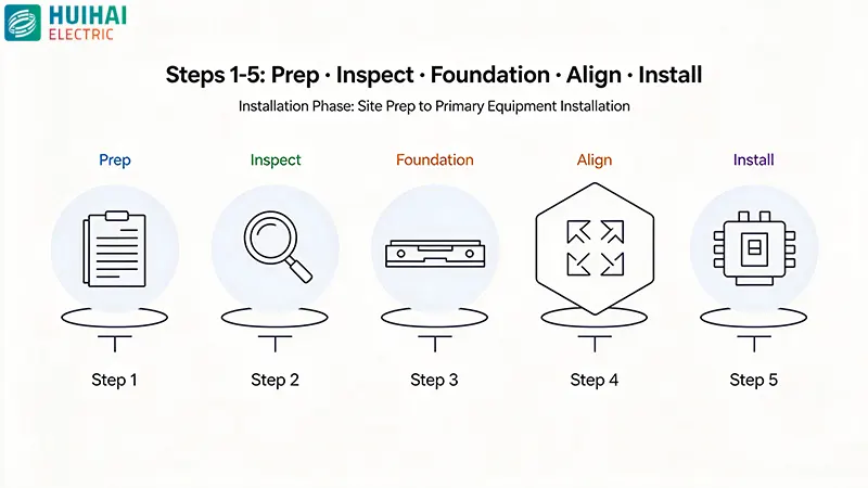
5. Primary Equipment Installation — Busbars, Breakers, and Cables
This step establishes the main power transmission path. Precision and cleanliness are critical.
What to do:
- Install circuit breakers and disconnectors — Ensure visible handles and clear isolation gaps.
- Install busbars — Clean all contact areas of busbars and feeder bars. Apply conductive paste to prevent oxidation and ensure conductivity. Use busbar bending tools for accurate shaping.
- Connect power cables — Strip cable insulation precisely, secure terminals tightly with proper torque, and fasten heavy cables with ties.
Critical checks:
- Contact resistance testing is crucial—it verifies the integrity of connections between modules and confirms correct phase sequence.
- For fully enclosed switchgear like GIS, main circuit resistance testing is essential.
6. Secondary Equipment Installation and Control Wiring
Secondary circuits—protection relays, meters, indicators, and control systems—require precision and clear identification.
What to do:
- Mount relays, meters, and indicators on panels using appropriate hardware.
- Pull in control cables from the bottom, strip ends, and insert into terminal blocks.
- Label wires clearly with color coding for phase distinction.
- Test insulation with a megohmmeter after wiring completion.
For GIS:
- Ensure proper wiring, sizing, and grounding of current transformers (CTs) and voltage transformers (VTs).
- Verify fail-safe electrical interlock schemes and provision of spare contacts for auxiliary relays.
7. Grounding System Installation
Proper grounding is essential for personnel safety and equipment protection. High voltage switchgear requires a dedicated, robust grounding system.
What to do:
- Install a dedicated earthing conductor — A grounding copper busbar should run along the entire length of the switchgear.
- Verify cross-sectional area — Must meet thermal stability requirements for fault grounding current.
- Connect main earthing bar to the station earth at multiple points—at the start and end of the installation, and at every second or third panel.
- Install dedicated earth collector bar around the switchgear room, connected to the cable basement collector bar at multiple points.
- Ensure visible grounding marks on all grounding connections.
For GIS: The grounding switch's main grounding connection must be rated to carry the peak withstand current rating for 1 second.
8. Gas Handling (For GIS Equipment)
For gas-insulated switchgear, gas handling is one of the most critical—and most sensitive—aspects of installation.
What to do:
- Follow IEC 62271-4 procedures for handling insulating and switching gases during installation and commissioning.
- Install adsorbent (4A molecular sieve) — Dry in a vacuum oven at 200–300°C for 12 hours. Install into the chamber within 15 minutes of drying.
- Begin vacuum processing immediately after chamber assembly. Install a check valve in the connecting pipeline to prevent pump oil backflow.
- Monitor gas pressure and density — Adjust to specified values.
- Perform leak testing and calibrate gas pressure gauges.
- Test functionality of gas density switches.
Critical control: For SF6 gas, moisture and impurity control is paramount. Once a gas chamber is opened, vacuum processing should proceed continuously to minimize exposure time.
9. Cold Commissioning — Pre-Energization Tests
Before applying high voltage, comprehensive off-load testing verifies that the installation is mechanically and electrically sound.
What to do:
- Visual inspection — Check for loose connections, proper grounding, and any signs of damage or improper installation.
- Mechanical operational tests — Perform multiple racking-in/racking-out and open/close operations for circuit breakers, disconnectors, and earthing switches.
- Insulation resistance testing — Measure winding-to-winding and each winding-to-ground.
- Contact resistance testing — Verify all primary connections.
- Partial discharge measurement — Detects insulation defects before energization.
- Timing tests for circuit breakers, disconnectors, and earthing switches.
- Functional tests for trip-free and anti-pump circuits.
- Polarity tests on current transformers and voltage transformers.
- Verify all off-load test documentation is formally completed.
For AIS switchgear: Testing and commissioning should follow organized procedures in accordance with IEC/IEEE standards.
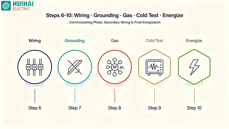
10. Hot Commissioning — Energization and On-Load Verification
The final step—energization—must be executed with extreme caution and a systematic sequence.
What to do:
- Prepare for energization — Confirm all off-load tests are complete and documented. Ensure all personnel are clear of the equipment.
- Apply auxiliary and control voltage first.
- Perform soak test — Energize the switchgear at no load for a specified period to verify stable operation.
- Energize radial circuits in sequence.
- Verify phasing using phasing sticks or voltage detectors.
- Test protection response — Verify all protection relays trip and alarm as configured.
- Commissioning Engineer should manually test circuit breaker operations, time switching actions, fine-tune components, and use a multimeter to assess operational values.
Final documentation:
- Complete all commissioning test reports
- Record all test values and observations
- Ensure handover documentation is prepared for the client
Summary: The 10-Step Installation Checklist
| Step | Phase | Key Activities |
| 1 | Preparation | Documentation review, team assembly, site readiness |
| 2 | Unpacking & Inspection | Damage check, component verification, certification review |
| 3 | Foundation | Level verification, channel steel preparation, shimming |
| 4 | Positioning | Panel placement, vertical alignment (≤2mm), bolting |
| 5 | Primary Equipment | Busbars, breakers, cables—clean, paste, torque |
| 6 | Secondary Wiring | Relays, meters, control wiring—label and test |
| 7 | Grounding | Dedicated earthing conductor, multiple connection points |
| 8 | Gas Handling (GIS) | Adsorbent drying, vacuum processing, leak testing |
| 9 | Cold Commissioning | Mechanical tests, insulation, contact resistance, PD |
| 10 | Hot Commissioning | Energization, soak test, phasing, protection verification |
Why Choose Huihai Electric for Your High Voltage Switchgear Needs
At Huihai Electric, we understand that switchgear installation is only as good as the equipment you start with. Our high voltage switchgear portfolio—available in both Gas-Insulated Switchgear (GIS) and Air-Insulated Switchgear (AIS) configurations—is designed and manufactured to meet the most stringent international standards, including IEC 62271 and IEEE C37 series.
What sets Huihai Electric apart:
- Full type test reports from accredited independent laboratories
- Rigorous quality control throughout manufacturing
- Comprehensive documentation including installation manuals and test reports
- Global technical support for installation and commissioning
- Customizable configurations to match your specific project requirements
Whether you are upgrading a utility substation, expanding industrial power distribution, or integrating renewable energy, Huihai Electric delivers reliable, high-performance switchgear solutions backed by decades of industry expertise.
Ready to specify your next high voltage switchgear project? Contact Huihai Electric to discuss your requirements, request technical documentation, or schedule a factory visit.
Written by
Huihai Electric Co., Ltd.
Editor Xu
www.huihai-electric.com
WhatsApp:+86 139 1136 0187
Email:info@huihai-electric.com
- Avoid Costly Mistakes: 8 Dry-Type Transformer Specs to Verify Before Purchase
- The 9 Key Roles of Dry-Type Transformers in Modern Smart Grid Infrastructure Construction
- The 9 Core Roles of Huihai Electric Prefabricated Substations in Photovoltaic Power Generation Systems
- High Voltage Switchgear Supplier Evaluation: 6 Critical Quality KPIs for B2B Buyers
HUIHAIElectric
Huihai Electric is a leading manufacturer of smart grid equipment in China.